Products


Site Designed And Maintained By: 
 
The Eagles Nest Internet Services 
Hand Holding Support For Sites That Work
 
RMW-115

RMW-115

RMW-115
RMW-115


MULTI-TASK RAILWAY MACHINE


  • SPECIFICATIONS
    • - 420 Bar closed loop independent hydrostatic (automotive) transmission on front axle, with variable displacement pump and motor.
    • - Maximum speed up to 16 mph.
    • - Theoretical gross tractive effort at the wheel 9,040 lbs.
    • - Maximum traveling slope on rails: 34.5%.
    • - Service brake and parking brake integralwith the rear axle.
    • - Idle rear axle.
    • - Modular railway-type wheels made from forged steel, diameter: 20 in.
    • - Mechanical and electric safety stop for revolving turret, to prevent rotation on the train traveling side.
    • - Manual emergency pump to operate the booms and turret, to use in the event of a failure to fold the machine back into the railway template within the preset time.
    • - Load sensors on the wheels to indicate the the overturning equilibrium limit has been reached during the loader operation phase.

1. RAIL DRIVE
1/a
The usual system to drive the machine on rails is the buggy wheel system. However it decreases the lifting capability of the machines since it forces the axles gauge to the rails gap. Also, sooner or later, some rubber tents to cover the buggy wheels causing causing electrical insulation of the machine on top of the rails.

1/b
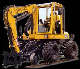
The RMW-115, is designed for multi-purpose targets, has a very compact shape and boom kimatics to face successfully every kind of operative condition on and off rails. Furthermore, this machine has been provided of peculiar double rail driving system, the way to increase the multi-purpose nature on rails. The driver is able to choose among:
1) 4 motive tires on rail drive (rail-wheels still on rails)
2) 4 motive tires on ground drive (rail wheels still on rails as well)

1/c
In order to warrant a mininum gap of 5 in. between the rail flat and the bottom part of the lower, the rail wheels have a minimum pitch diameter of 20 in. They are manufactured according to European standards (see drawing 1/c) and can be modified on demand.

1/d
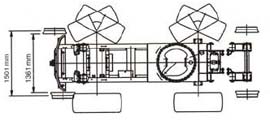
In order to get the minimum wear when skippong obstacle on rails, to warrant safe motion on roads and operate efficiantly off roads, the machine is provided with Michelin 12.00 R20 X MINE D2 type tires (see drawing 1/d).
1) On standard condition, the tires are mounted on inner position and the distance between the tires is 56 in. and the outer 82 in. mm. This allows the machine to operate with 4 motive tires on rails while it keeps loading on the rails (narrow gauge configuration).
2) Just turning the tires mounting flanges, the tires become larger than the rails and allows the machine the most stability features during lifting operations while it keeps loading on the rails. The inner distance between the tires becomes 70 in. and the outer 96 in. (wide gauge configuration). (see drawing 1/d_1).
3) The steering system can be locked, just turning on a switch placed in the cab.

1/e
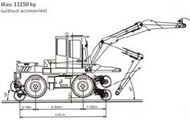
The machine on rails can reach a maximum speed of 12.5 mph (up to 15.5 mph on demand) and is provided with a braking system able to stop the machine within the terms stated by the European rail standards

Drawing 1/c
Drawing 1/c - In order to warrant a minimum gap of 5 in. between the rail flat and the bottom part of the lower, the rail wheels have a minimum pitch diameter of 20 in.
Drawing 1/c
Drawing 1/c
Drawing 1/d
Drawing 1/d - Michelin 12.00 R20 X MINE D2 type tires.

INCREASED PRODUCTIVITY
The ultra-deep L5 rock tread with massive buttressed shoulders and sidewalls provide reisistance to damage in severe operating conditions.

LONG TIRE LIFE
The combination of multiple steel belts, cut-resistant rubber compounds and a heavy-duty casing means fewer flats.

MAXIMUM COMFORT AND MACHINE PROTECTION
The Michelin radial design helps protect valuable machine components while giving operators a smooth, comfortable ride. It eliminates the need for expensive foam/poly fill or chains.

Drawing 1/d
Drawing 1/d
Table 1
Table 1
Drawing 1/d_1
Drawing 1/d_1 - On standard condition, the inner distance between the tires is 1,414 mm and the outer is 82 in.; this allows the machine to operate 4 motive tires on rails while it keeps loading on the rails (narrow gauge configuration). Just turning the tires mounting flanges, the tires become larger than the rails and allows the machine the most stability features during lifting operations while it keeps loading on the rails; the inner distance between the tires becomes 70 in. and the outer is 96 in. (wide gaufe configuration).
Drawing 1/d_1
Drawing 1/d_1